
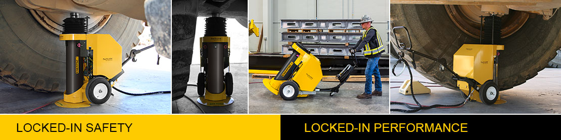
New Pow'R-LOCK Self-Locking Portable Lift System
Enerpac is proud to introduce the Pow’R-LOCK™, a self-locking jack that performs automatic mechanical locking during lifting, lowering and holding. A patent-pending control system provides full-time automatic locking, securing the load regardless of cylinder movement and control cycle. No need to manually lock or release the load; the operator just selects lift or lower on the remote pendant and Pow’R?LOCK™ does the rest.
Rated lifting capacity: 200 tons (1779 kN)
Stroke: 14 or 25 inches (356 or 622 mm)
Maximum operating pressure: 10,000 psi (690 bar)
Meets AS/NZS?2538, AS/NZS?2693 and ANSI B30.1-2009 Certification criteria
Efficient lifting with continuous, automatic load locking
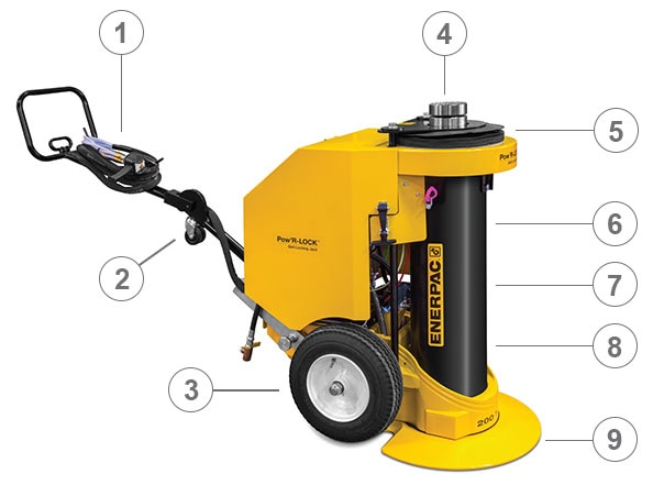
1) Easy to use 2-button pendant allows remote operation from up to 20 feet away, keeping the operator out from under the load.
2) Caster wheel allows easy positioning under the load.
3) Large, air-inflated durable primary tires for easy transport.
4) Standard serrated tilt load cap allows proper engagement with the load to reduce
5) Flexible plunger boot guards the lock nut and plunger from debris
6) Exclusive load locking jack is designed to resist side load damage.
7) Nitrocarburization of lock nut, cylinder base, plunger and retract piston provides additional corrosion protection and durability.
8) Unique double-acting cylinder offers a low collapsed height to accommodate more lifting applications.
9) Large base plate distributes the load over a larger area, reducing ground pressure and increasing stability.

A simple 2-button pendant allows remote operation of raise and lower functions.

Tilt load cap reduces side-loading.

The extended ergonomic handle has six positions for comfortable handling and folds when not in use.
Patent-pending control technology synchronizes cylinder and locknut for smooth and efficient lifting and lowering.
All load bearing cylinder components have a nitrocarburized treatment to improve wear characteristics and resist corrosion.
1) Locknut mechanically supports the piston at all times.
2) Retract Piston helps guide plunger and resists side-loads.
3) Chain Sprocket drives the locknut up and down.
4) Cylinder Stem delivers hydraulic fluid to top of piston to retract the plunger.
5) Bronze Bearing resists higher side-loads.

How automatic and continuous load locking is achieved
Pow’R-LOCK has been designed with unique safety features so that a load cannot be lifted without the jack being locked. The unit's locknut mechanically supports the piston during lifting and lowering. Load locking is automatic and does not require any manual intervention, a feature unique to Pow’R-LOCK. If there is any type of hydraulic failure, the locknut will still be supporting the load, preventing uncontrolled lowering of the load.
1) During lifting, the drive sprocket spins the chain which drives the locknut downward, ensuring continuous locking.
2) The locknut always rests on the cylinder base during lifting, so the load is never supported strictly by the hydraulics.
3) During lowering, a proprietary air logic system advances the cylinder a bit before retracting to lift the locknut off the cylinder base. When the locknut has raised sufficiently, a sensor reverses the cylinder's direction, and the locknut is allowed to spin upward. The threads between the locknut and plunger always remain engaged.
4) Multiple sensors are built into the jack to ensure proper orientation between the locknut and the top of the cylinder. If proper orientation is not maintained, the jack stops lifting - and the load remains supported.

Load locking technology overview video
As the jack raises, the locknut spins down against the cylinder base continuously locking the jack. This type of locking is optimal compared to ratchet-type locking where a load can drop down to the last ratchet point. With Pow'R-LOCK the load locking mechanism is always engaged; if the jack shuts down for any reason, uncontrolled lowering is prevented.
Safety First: When lifting large, heavy vehicles certain precautions must be followed. Always follow your published safety directions for lifting and cribbing your loads.

Standard low profile load cap for tight lifting spaces.

Extension base adapter design eliminates risk of improper stacking when using more than one extension.
Spacers: 1" and 2" (25.4 &52.1 mm) minimizes gap between load cap and lifting point to maximize hydraulic stroke of the jack.

Extensions: 5", 7", 9", 11" & 14" (127, 178, 229, 279 & 356 mm) Large alloy steel locating studs resist effect of side-loading.